|
The History of
MID-LIFT®
INTRODUCTION
MID-LIFT®
was developed from a study of the
most complex valve train of any American made engine of its time: the
BOSS 429 Ford Hemi. It's founder received
the only US Patent ever issued for a concept of rocker arm geometry. The
MID-LIFT Patent,
as it became known by, covered every type of OHV engine: automotive,
marine, motorcycle and even aircraft. But MILLER only made rockers for
the BOSS engine in limited quantities, so well advertised brands for
more popular engines were never challenged. But arguably it has been an
embarrassment to many fine companies of the valve train industry for
more than 20 years. The following story has been published for many
years... and never contested.

MID-LIFT®
How it Began
---By
Michael
O'Hara
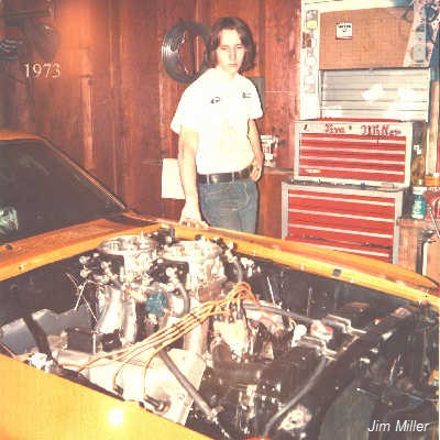
In 1973, 19 year
old Jim Miller, a weekend racer and
professionally serious engine
builder, needed a better rocker system to improve the valve train on his 9,300
rpm mid-9 second 1970 BOSS 429 Mustang;
his second BOSS 429 in
two years, after flipping his
original BOSS 429 end-over-end in 1972.
There was only one shop making
such a rocker arm for Jack Roush; they were large and looked too heavy. Concluding he would
need
to make his own, Jim began to study the roller rocker arms of other companies
which he used on his customers Chevrolet and Ford engines, trying to understand
the various parameters being used for rocker arm design. What he found was
confusing and illogical. The Rocker arm dimensions were different from one manufacturer
to the other, for the same make and model engines. The trunnion center-to-centers and the angle of the
pushrod cup with the pushrod were all over the place. In some cases, the same manufacturer used
different specifications for the same application. While several companies used
the same dimensions for engines of different specifications, merely re-stamping
them; a practice that continues to this day. Those
inconsistencies forced Jim into a long study of nearly every roller rocker arm
of that era. Old, new, factory stock, aluminum and so on.
Nearly a year later, his initial
suspicions were confirmed - there was no standard. The errors revolved around
what Jim dubbed "design geometry," the rocker arm's relationship with the
pushrod angle and the valve, which was unique to each engine. In addition, the
manufacturers making the rocker arms had no real technical information on their
correct installation. All of Jim's questions were responded to with vague
answers, like: "make sure the roller is in the middle of the valve," or..."as
long as nothing hits anything it's alright." But it wasn't alright. He
discovered similar problems, years earlier on the 427 Mustang, a factory shaft
system. He new merely rotating the height of the adjusting screw up and down
would change the net valve lift and duration. Raising stand heights and juggling
pushrod lengths was unheard of in 1970, but his experiments here compounded the
dynamics even further. The people Jim routinely did business with didn't offer
much advise. People like: Wayne Gapp & Jack Roush, "Dyno" Don Nicholson, and
NASCAR moguls Holman-Moody, all had similar indifference.
Without any standard to follow, Jim
applied logic, a 90 degree concept to the valve side of the rocker arm, then
added the same principle to the pushrod side, noting the different consequences
if ignoring one or the other. Having outlined the principles on paper, attention
was turned to his real need, which was one of the most complicated valve trains
to have ever come out of Detroit. Ford's
BOSS 429
had the shortest intake rocker arms of any V8, while in contrast one of the longest exhaust rockers was
operated by extremely angled pushrods well over 10" long. With the rocker arms
mounted on individual shafts and stands, each laid over on a compound angle,
even more questions were tackled to apply an efficient design that would operate
opposing valves twisted on a 64 degree angle to the piston pin. It was a
challenged and a study that would lend a novel insight to the valve train
geometry which no other American made engine of that era could provide.
|
 |
Jim Miller
(1978),
inspecting one of the Series II MID-LIFT BOSS 429 Exhaust rockers.
Around 1980, a special ratio
of this same rocker arm would be ordered by NHRA's Pro Stock World
Champion, Bob Glidden. Bob used a
de-stroked version of the BOSS Hemi engine in his quest to regain a
more favorable weight break over
his dominating 351ci Cleveland.
|
THE SECRET
The other companies designed their
rocker arms in a "closed valve" state, with regard to only fitting the head,
not
the engine, thus disregarding the pushrod's influence with the valve. What Jim
Miller did that was novel, was to design the rocker arm's tangent points when BOTH the valve and the
cam were in the MID-LIFT position simultaneously. This
influenced all of the critical dimensions and equally divided the rocker arm's
circular motion (arc) on BOTH sides, which Jim emphasized was critical to not
only minimizing
back-and-forth sweep atop the valve, but providing the maximum information of
the cam dynamics to the rocker arm with the ultimate least amount of wasted motion.
This additional motion, found in all previous rocker manufacturers, required the
crank to turn additional degrees of rotation to effect the same amount of cam
lift "at the rocker arm." Miller's MID-LIFT principle of design set in stone a
formula that would apply to any valve lift,
provided the engine builder set the "installed geometry" for the net valve lift
of the engine, a mandatory task with any rocker. Finally, a standard! And in
1974, the phrase Jim kept using was coined: "Mid-Lift" becoming the terminology
to a Patent application in 1978, that was filed in 1980 and issued in 1982. The
MID-LIFT Patent: #4,365,785.
How could this be, how could an
industry of multi-million dollar cam companies make such an oversight? When
you're 20 years old, it's hard to appreciate the value of such a discovery,
especially if you don't know how it was missed. Finding the answer to this
confounding question became necessary. Within a year the answer would be known.
In early 1974, Jim flew to Ohio for a meeting with the founder of the
"original aluminum roller tip rocker," a man he respected, who would, from time
to time do custom work for Jim. In that meeting and the correspondence that
followed, the link to the error was made. "It was so logical," Jim recalls,
"...it blew me away, anyone could have done it." The story goes like this...
In 1958, Harland Sharp, an
avid automotive enthusiast and hard working, innovative machinist, took a
standard OEM stamped steel "shoe" type rocker arm and laid it on its side to
trace its silhouette on a piece of paper. Knowing he wanted to place a roller
tip on the end, he traced a roughly .600" diameter roller, placing the bottom of
the roller's diameter on the same horizon as the shoe's contact pad of the
original rocker arm. This was the mistake. He marked a center to this circle for
the location of the roller pin, then using a scribe, he transferred his
silhouette to a block of aluminum where he proceeded to machine his roller tip
rocker body. Several years later, Harvey Crane asked Harland to make roller
rocker arms for his company: CRANE CAMS. However, within a short period of time,
Crane's excellent national marketing outstripped Harland's production
capability, forcing CRANE to use other sources, eventually making them in-house.
Having already established an identity with Harland's roller rocker arms, CRANE
simply kept the same design basics which Sharp had been using, and the mistake
was copied. During the 1960's, several of today's top cam companies began making
their own line of rocker arms, and although many would no doubt argue that their
design was unique to their own ideas, the fact of the matter is: that same
mistake appears to have been copied throughout the industry... and except for
some copy-cats pretending they have a "better geometry," it continues to
this day. True story!
^
THE ERROR
What was it?...
In much the same way the designing of a flat tappet cam is measured differently than the roller
tappet cam, so
too is the principle of design with a roller tip rocker arm. For on a "shoe"
rocker arm, it is the bottom contact pad that has traditionally been used for angular measurement
with the axis of the fulcrum (trunnion or shaft), but with a "roller tip" it is the axis of the
roller that is used for angular motion. By placing the bottom of the roller on
the same horizon as the shoe, the measurement was off by half the diameter of
the .600" roller, or .300". In angular terms on the small block rocker arm, this works
out to more than 12 degrees of error. To set this in perspective, the rocker arm
only moves 24 degrees or so for a valve lift of .600" making the rocker arm
wrong by 50% of its motion, regardless of the pushrod length or the rocker's
height to the valve tip!
|
 |
Line "A"
represents the contact pad of the rocker,
traditionally used for rocker design under the "1/3
RULE."
But with roller tappets or roller rockers it is the axis of the
roller which matters, not the outer diameter, which is what Harland used, as
shown. This moved the roller axis up by half of its .625"
diameter. This extra .312" error had the effect of moving the
push rod "cup" UP (shown as "C") by more than 12 degrees.
The rocker arm
only moves about 24 degrees, so no matter what pushrod length you choose, only one
side of the rocker arm can be set for minimal back and forth
motion, while the other end suffers. "B" represents this increased
angle with "C" while the dashed line beneath "C" shows where MID-LIFT geometry should be.
CLICK ILLUSTRATION FOR MORE DETAIL.
|
Note:
The late Harland Sharp's background with
racing interests dated back to the 1950's, when many of today's largest and
most well known companies were first beginning. The hand written notes and
drawings from Harland, during the 1970's when he made custom designs for Jim
are still kept as a reminder to the simple legacy of this history.
^
MILLER MID-LIFT™
The Standard By Which All Is Measured!™
954-978-2171 MillerRockers@aol.com
MID-LIFT™, PRO-SHAFT™ & PRO-STUD™ are JM Miller Trademarks; Copyright © MMIII~MMXXIV
| |