|
The
Inspiration of MID-LIFT®
Rocker Arms
This is where all MID-LIFT®
geometry has evolved from since it was developed ...more than 43 years ago!
|
(FOR MODIFIED 1980 BOSS
MANIFOLD CLICK PHOTO)
|

(FOR BOSS ROCKERS CLICK PHOTO) |
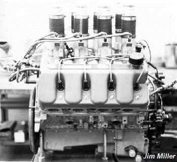
Ford's
BOSS 429 crossed over
into CAN AM racing, displacing 494 cubic inches. It's torque was phenomenal,
prompting quite a few of these FIRST aluminum block Ford BOSS engines to be
used in pursuit boats, sold to Arab nations; similar to Scarab (Miami Vice)
style boats, with two and three engines each. Ford's independent Grand
National contractor, Holman-Moody, was behind all these famous variations,
and many other of Ford's exotic racing endeavors.
|
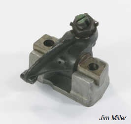
Miller
BOSS 429 Series III Rockers
(1983). Jim Miller was the FIRST designer who
understood the detriment of side thrust harmonics and their loads upon compound
geometry valve trains. Jim has used Torrington Thrust bearings since 1983,
and implemented them on all
PRO-SHAFT NASCAR designs whenever any side load
inclines from the push-rods was evident on the head's X-axis. But it was on
the extreme angled BOSS 429 where they were developed and used first.
|
The Roots of MID-LIFT
originates from the most complex valve train of any American racing engine!
(Everything else is easy.)
BOSS 429 Ford
"BLUE CRESCENT"
Designed in 1968, implemented in 1969, the
BOSS 429
was Ford Motor Company's answer to their failed attempt to introduce the
Over-Head Cam 427 Side Oiler into NASCAR's Grand National racing, and regain
their competitive edge against Chrysler's dominant 426 Hemi. Ford took their
"attitude" for overkill engineering originally directed into the 427 SOHC, and
took NASCAR's no over-head-cam rule to the recently new block
originally designed for the truck and big car market, known as the
"385 Series," for its 3.85" stroke crank; but it was more familiar as the
"460." It was soon de-stroked to a 3.59" crank and adapted as the 429 wedge,
429CJ, and 429SCJ. All these basic variations followed a common cast iron
cylinder head canted valve array, including a few quirk aluminum head castings
based on the SCJ. They were very similar to the Chevy 427 combustion chamber, except
all intake ports were parallel designs (not symmetrical - left and right
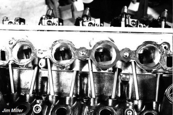
variations, as the BB Chevy). The BOSS 429 "head" was adapted to this engine
block, but only after some oil galley and deck transfer holes were engineered to
be precision machine for the novel individual gasket rings. The BOSS 429 sported many conceptual ideas of airflow from the 427 SOHC,
and 427 TUNNEL PORT, mainly round intake ports, but HUGE (for their time); a
hemispherical combustion chamber, that was "clipped" on each side just a tad,
creating a design that was coined "semi-hemi" and "crescent" -- and later became
known as the BLUE CRESCENT Hemi. Where Ford really got complex, was their
initiative to introduce a flow technology that had been briefly tested on more
exotic engine designs, but never an American OHV engine. It was later coined as "swirl"
technology. One of the concepts to swirl technology is to purposely place the
valve angles and their related port windows feeding them (as well as the port
shape) in such a manner that a preset direction of flow is used to do more than
just fill the chamber. It induces a cross-flow over the piston and to move
across to the
exhaust valve which sets up a circular pattern of chamber burn and purging. The
aim is more efficient flame propagation, which wedge chambers are good at, but
lack in the cross-flow efficiency to purge as well as a hemi. To accomplish
this the BOSS 429 had its opposing intake and exhaust valve axis rotated 26°
from perpendicularity to piston wrist pins. This required considerable creative thinking
for passing the pushrods through the heads for complex mounting angles of the rocker arms. Unlike the 427
Tunnel-Port, where they simple went straight through the port with surrounding
sleeves to isolate the two systems, the valve train was laid over on compound
angles, which I have stated many times is the most complex rocker geometry of
any American made Overhead Valve (OHV) engine, ever; even to this day, nearly 50
years later.
--jM
(Revised, 2016)
^

The concept of MID-LIFT® geometry began
back in 1973, and by 1974 it was finalized into the principles of
precision geometry that Jim Miller developed for the Ford's BOSS 429
Grand National NASCAR engine. You don't have to be a
"Ford fan" to appreciate that in 1968, when this engine was first taken from the
drawing boards of Ford's racing division to a real engine for racing in 1969, it
had set a precedent for airflow, volumetric efficiency, horsepower per cubic
inch, and sheer, all out "WOW" factor, that no other engine of that era had
done. But it was flawed in a couple of small respects.
One, was its valve train.
COMPLEX. Meaning: it was a semi-hemispherical combustion chamber, with quenched side
walls to contain the cross flow intentions of a hemi chamber, but the intake to
exhaust valve's opposing angles were "twisted" on a 26 degree rotation to the
piston's wrist pin. The rocker arms were independently mounted on pedestals cast
and machined at precise compound angles. But like another engine Ford made the
same mistake with, the attachment to the block for pushrod angles was required
to work with lifters that were "in-line" rather than laid over for dedicated
exhaust and intake rocker locations. Plus, the pushrod's side angle array was
heavily leaned away from the tappet centerlines too.
^
 |
 |
|
Factory INTAKE |
Factory EXHAUST |
The cylinder head's huge round
ports and location, required this twisting of the valve to valve centerlines,
but Ford was also chasing induced swirl technology, very new for OHV engines of
that period. But to make all the parts fit between where the pushrods would exit
through the heads, and the valve tips needed to be, meant that the rocker arm
dimensions would be extreme in both directions. The INTAKE rocker was one of the
shortest designs used on any American engine, rivaling the small block
Chevrolet. The EXHAUST rocker was the longest, exceeding the Chrysler
hemi. The pushrods themselves were also among the longest in use, with the
exhaust reaching nearly 11" in length.
^
In 1972, for "Grand National"
racing (as Winston Cup style NASCAR was known in those days), the typical 7,800
rpm hemi engines with barely .650" valve lift could accept these crazy
valve-train arrays. But drag racing's high rpm, quick shock to the drive train
was entirely different. For Jim Miller's de-stroked 409ci B/MP BOSS Mustang,
that launched from the line at 9,000 and hit the 1/4 mile traps at 9,300 rpm; no such
designs were possible, without breaking something on each pass. This was the beginning of
questions for an engine few people understood, compared to the masses of
information accrued over the years for Chevrolet and Chrysler engine builders.
Rocker arm questions, for instance. To begin designing his own rockers, Jim
needed a foundation from how other designs were done. But even
questions asked with the common Chevrolet engines, Jim Miller soon learned there
was no comparable dimensions for various manufacturers on their rocker arms.
Center-to-center lengths for the critical stud to valve, as well as the arcing
motion across the valve, were all undecided specifics between individual
manufacturers. Rocker arm "height" on the stud (or shaft, as in the Ford 390-428
FE engine) was also a question that no cam manufacturer selling rocker arms
would answer, beyond "keep the rocker on the tip of the valve."
^
MILLER MID-LIFT™
The Standard By Which All Is Measured!™
954-978-2171 MillerRockers@aol.com
MID-LIFT™, PRO-SHAFT™ & PRO-STUD™ are JM Miller Trademarks; Copyright © MMIII~MMXXIV
| |